
WINGONEER TB6560
WINGONEER TB6560 3A Single-Axis Stepper Motor Driver Board User Manual
Introduction
This manual provides detailed instructions for the installation, operation, and maintenance of the WINGONEER TB6560 3A Single-Axis Stepper Motor Driver Board. Please read this manual thoroughly before using the product to ensure proper function and safety.
Коопсуздук маалыматы
- Ensure power is disconnected before making any wiring connections or adjustments.
- Operate the board within the specified voltagзыяндын алдын алуу үчүн д жана учурдагы чектөөлөр.
- Avoid touching components while the board is powered, especially the heatsink, as it may become hot.
- This device is intended for use by individuals familiar with electronics and stepper motor control.
Продукт бүттүview
The WINGONEER TB6560 3A Single-Axis Stepper Motor Driver Board is designed for controlling a single stepper motor. It features adjustable current settings and microstepping capabilities, making it suitable for various applications requiring precise motor control.
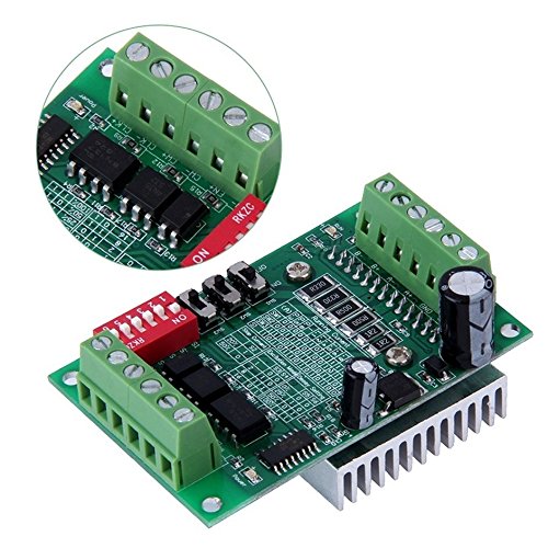
1-сүрөт: Үстүнкү бурч view of the TB6560 driver board, highlighting the terminal blocks for motor and power connections, as well as the DIP switches for configuration.
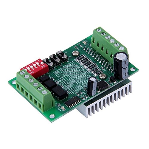
2-сүрөт: Бурчтуу view of the TB6560 board, showing the heatsink attached to the TB6560 chip, which is crucial for heat dissipation during operation.

3-сүрөт: Төмөнкү view of the TB6560 driver board, illustrating the printed circuit board (PCB) layout and the underside of the heatsink.
Техникалык шарттар
| Өзгөчөлүк | Нарк |
|---|---|
| Бренд | WINGONEER |
| Тtage | 10 Volts, 24 Volts (Operating Range) |
| Материал | Plastic (Board components) |
| Элемент Салмагы | 73 грамм (2.57 унция) |
| Өндүрүүчү | WINGONEER |
| UPC | 723466639095 |
| Пакеттин өлчөмдөрү | 4.72 x 4.09 x 0.94 дюйм |
Орнотуу жана орнотуу
1. Зымдарды туташтыруу
Before connecting any wires, ensure the power supply is disconnected. Refer to the board's labels for correct polarity and pin assignments.
- Электр камсыздоо: Connect a DC power supply (10V-24V) to the designated power input terminals. Observe polarity: V+ for positive, V- for negative.
- Stepper мотору: Connect your 4-wire or 6-wire stepper motor to the motor output terminals (A+, A-, B+, B-). For 6-wire motors, the center taps are typically left unconnected or connected as per specific motor requirements.
- Башкаруу сигналдары: Connect your control signals (STEP, DIR, ENA) from your microcontroller or CNC controller to the corresponding input pins on the driver board. Ensure a common ground connection.
2. DIP Switch Configuration
The TB6560 board features DIP switches to configure the output current and microstepping resolution. Always adjust DIP switches when the board is unpowered.
Учурдагы жөндөө
The output current can be set using a combination of DIP switches. Refer to the silkscreen on the board or the following table for common settings. The maximum current is 3A.
| DIP которгуч 1 | DIP которгуч 2 | Output Current (Approx.) |
|---|---|---|
| ON | ON | 100% (e.g., 3A) |
| ӨЧҮРҮҮ | ON | 75% (e.g., 2.25A) |
| ON | ӨЧҮРҮҮ | 50% (e.g., 1.5A) |
| ӨЧҮРҮҮ | ӨЧҮРҮҮ | 25% (e.g., 0.75A) |
Note: The exact current percentage may vary slightly. Always match the current to your stepper motor's rated current to prevent overheating.
Microstepping Setting
Microstepping allows for smoother motor operation and finer resolution. The TB6560 supports full step, half step, 1/8 step, and 1/16 step modes.
| DIP которгуч 3 | DIP которгуч 4 | Microstepping Mode |
|---|---|---|
| ON | ON | Толук кадам |
| ӨЧҮРҮҮ | ON | Half Step |
| ON | ӨЧҮРҮҮ | 1/8 кадам |
| ӨЧҮРҮҮ | ӨЧҮРҮҮ | 1/16 кадам |
Note: Higher microstepping values result in smoother motion but may require higher step pulse frequencies from your controller.
Иштөө нускамалары
- Баштапкы кубаттоо: After all connections are secure and DIP switches are set, apply power to the board. The power indicator LED should illuminate.
- Башкаруучу сигнал киргизүү: Send STEP pulses to the STEP input pin to move the motor. The DIR pin controls the direction of rotation. The ENA (Enable) pin, when active (typically low), enables the motor driver.
- Motor Movement: Observe the motor's response. If the motor does not move or moves erratically, refer to the Troubleshooting section.
- Өчүрүү: Always disconnect the power supply before making any changes to wiring or DIP switch settings.
Техникалык тейлөө
- Тазалоо: Keep the board free from dust and debris. Use a soft, dry brush or compressed air for cleaning. Do not use liquid cleaners.
- Экологиялык шарттар: Operate the board in a dry, well-ventilated environment. Avoid extreme temperatures and high humidity.
- Жылыткыч: Ensure the heatsink remains clear of obstructions to allow for efficient heat dissipation. Periodically check for dust buildup on the heatsink fins.
Проблемаларды чечүү
| Көйгөй | Мүмкүн себеп | Чечим |
|---|---|---|
| Мотор кыймылдабайт. | No power, incorrect wiring, ENA pin disabled, no STEP pulses. | Check power supply, verify all wiring connections, ensure ENA is active, confirm STEP pulses are being sent. |
| Motor moves erratically or skips steps. | Insufficient current, excessive speed, incorrect microstepping, loose connections. | Increase current setting (if safe for motor), reduce step pulse frequency, verify microstepping settings, check all connections. |
| Мотор ысып кетет. | Current setting too high, inadequate cooling. | Reduce current setting via DIP switches, ensure proper ventilation around the heatsink. |
| Плата күйбөйт. | Электр менен камсыздоо жок, үн туура эмесtage, reversed polarity. | Verify power supply connection and voltage, check for correct polarity (V+ to positive, V- to negative). |
Ask a question about this manual
Ask about setup, troubleshooting, compatibility, parts, safety, or missing instructions. Manuals+ will review the question and use this page’s manual context to help answer it.