
Supermicro MBD-X10DRG-O+-CPU
Supermicro X10DRG-O+-CPU Motherboard User Manual
Model: MBD-X10DRG-O+-CPU
1. Киришүү
This user manual provides comprehensive instructions for the installation, configuration, and maintenance of the Supermicro X10DRG-O+-CPU Motherboard. This motherboard is designed for high-performance computing environments, supporting dual Intel Xeon E5-2600 v3/v4 processors and extensive memory configurations.
Please read this manual thoroughly before beginning the installation process to ensure proper setup and operation.
2. Коопсуздук маалыматы
Always observe the following safety precautions when handling the motherboard and other computer components:
- Компоненттерди орнотуудан же алып салуудан мурун кубат булагы розеткадан ажыратылганын текшериңиз.
- Статикалык электр энергиясын чыгаруу үчүн антистатикалык билек боону тагыңыз же жерге туташтырылган металл нерсеге тез-тез тийип туруңуз.
- Сезимтал компоненттерге тийбеш үчүн, энелик платаны четтеринен кармаңыз.
- Keep the motherboard away from liquids and extreme temperatures.
- Refer to the safety guidelines provided with other components (CPU, RAM, etc.) for additional precautions.
3. Пакеттин мазмуну
Таңгактагы бардык буюмдардын бар экенин текшериңиз. Эгерде кандайдыр бир буюм жок болсо же бузулуп калса, дароо сатуучуга кайрылыңыз.
- Supermicro X10DRG-O+-CPU Motherboard
- I / O Shield
- SATA кабелдери (саны ар кандай болушу мүмкүн)
- Ыкчам маалымдама колдонмосу
- Драйвердин CD/DVD диски (же жүктөлүп алынган драйверлерге шилтеме)
4. Motherboard Layout
Төмөндө бүттүview of the Supermicro X10DRG-O+-CPU Motherboard, highlighting key components and connectors.
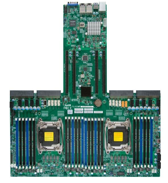
Figure 4.1: Supermicro X10DRG-O+-CPU Motherboard. This image displays the full motherboard, showing the dual CPU sockets, numerous DDR4 DIMM slots, PCIe expansion slots, and various I/O ports and connectors.
Негизги компоненттер:
- CPU Sockets (LGA 2011-3): Two sockets for Intel Xeon E5-2600 v3/v4 processors.
- DDR4 DIMM Slots: Multiple slots supporting up to 3072 GB of ECC DDR4 memory.
- PCIe кеңейтүү уячалары: Various PCIe 3.0 slots for graphics cards, network cards, and other expansion devices.
- SATA порттору: Connectors for SATA 3.0 storage devices.
- USB порттору: USB 2.0 and USB 3.0 headers and rear panel ports.
- LAN порттору: Ethernet ports for network connectivity.
- Power Connectors: ATX 24-pin, 8-pin EPS, and 4-pin power connectors.
5. Орнотуу
Энелик платаны жана анын компоненттерин туура орнотуу үчүн төмөнкү кадамдарды аткарыңыз.
5.1 CPU орнотуу
- Open the CPU socket retention levers.
- Процессордун үч бурчтук белгиси розеткадагы белгиге дал келишин камсыз кылып, CPU менен розеткага кылдат тууралаңыз.
- Процессорду мажбурлабастан акырын розеткага салыңыз.
- Close the retention levers to secure the CPU.
- Apply thermal paste and install the CPU cooler according to the cooler manufacturer's instructions.
5.2 Эстутум (RAM) орнотуу
- DIMM уячасынын эки учундагы клиптерди ачыңыз.
- DDR4 эстутум модулундагы оюкту DIMM уячасындагы ачкыч менен тууралаңыз.
- Модулду уячага бекем кысып, клиптер ордуна орнотулганга чейин киргизиңиз.
- Repeat for all desired memory modules, following the motherboard's memory population guidelines for optimal performance.
5.3 Сактагыч түзүлүштү орнотуу
- SATA маалымат кабелинин бир учун энелик платадагы SATA портуна туташтырыңыз.
- SATA маалымат кабелинин экинчи учун SATA катуу дискиңизге же SSDге туташтырыңыз.
- SATA кубат кабелин кубат булагыңыздан сактагыч түзмөгүнө туташтырыңыз.
5.4 Кеңейтүү картасын орнотуу
- Select an appropriate PCIe slot for your expansion card (e.g., GPU, network card).
- Компьютериңиздин корпусунан тиешелүү уячанын капкагын алып салыңыз.
- Кеңейтүү картасын уячага тууралап, ал толук орнотулганга чейин катуу басыңыз.
- Secure the card with a screw or retention clip to the PC case.
5.5 Кубат туташтыруу
- Connect the 24-pin ATX power connector from your power supply to the main power header on the motherboard.
- Connect the 8-pin EPS (CPU) power connector(s) to the corresponding headers near the CPU sockets.
- Бардык электр кабелдери коопсуз туташтырылганын текшериңиз.
5.6 Front Panel Connections
Connect the front panel cables (Power LED, HDD LED, Power Switch, Reset Switch, USB, Audio) from your PC case to the corresponding headers on the motherboard. Refer to the motherboard's silkscreen labels for correct pin assignments.
6. Иштөө
6.1 BIOS/UEFI орнотуу
Upon first boot, you may need to enter the BIOS/UEFI setup utility to configure system settings. Typically, you can access this by pressing DEL or F2 during the POST (Power-On Self-Test) sequence. Common settings to configure include boot order, date/time, and enabling/disabling specific features.
6.2 Драйверди орнотуу
After installing your operating system, install the necessary drivers for the motherboard's chipsets, LAN, audio, and other integrated components. Drivers can be found on the included driver CD/DVD or downloaded from the Supermicro official webсайт.
6.3 Операциялық системаны орнотуу
Insert your operating system installation media (USB drive or DVD) and follow the on-screen prompts to install the OS. Ensure the boot order in BIOS/UEFI is set to prioritize your installation media.
7. Техникалык тейлөө
7.1 Тазалоо
Энелик платадан жана анын компоненттеринен чаңды кысылган аба менен үзгүлтүксүз тазалап туруңуз. Тазалоодон мурун системанын өчүрүлгөнүн жана розеткадан суурулганын текшериңиз. Суюктуктарды же абразивдүү материалдарды колдонуудан алыс болуңуз.
7.2 Микропрограмма жаңыртуулары
Мезгил-мезгили менен Supermicro текшерип туруңуз website for updated BIOS/UEFI firmware. Firmware updates can improve stability, performance, and add support for new hardware. Follow the provided instructions carefully when performing a firmware update to avoid system damage.
8. Кыйынчылыктарды
Бул бөлүмдө сиз кабылышы мүмкүн болгон жалпы маселелерди чечүү жолдору каралган.
| Көйгөй | Мүмкүн себеп | Чечим |
|---|---|---|
| Система күйбөйт. | Бошогон электр кабелдери, туура эмес электр энергиясы, алдыңкы панелдин туура эмес туташуулары. | Check all power connections (24-pin, 8-pin EPS). Verify front panel power switch connection. Test power supply. |
| Дисплейдин чыгышы жок. | Incorrectly seated GPU, faulty monitor cable, no integrated graphics. | Reseat the graphics card. Check monitor cable connections. Ensure monitor is on correct input. |
| Система кайра-кайра бип сигналын берет. | Memory (RAM) issue. | Reseat RAM modules. Try one module at a time. Refer to BIOS beep codes for specific diagnosis. |
| Операциялык система табылган жок. | Incorrect boot order, loose SATA cable, unformatted drive. | Check BIOS/UEFI boot order. Reseat SATA cables. Ensure drive is properly formatted and OS installed. |
9. Техникалык шарттар
Detailed technical specifications for the Supermicro X10DRG-O+-CPU Motherboard.
- Модель номери: MBD-X10DRG-O+-CPU
- Бренд: Supermicro
- CPU колдоо: Dual Intel Xeon E5-2600 v3/v4 Processors (LGA 2011-3)
- RAM эс максималдуу өлчөмү: 3072 GB DDR4 ECC
- Системалык шина стандарты колдоого алынат: SATA 3
- S/PDIF туташтыргычынын түрү: Оптикалык
- Пакеттин өлчөмдөрү: 25 x 25 x 4 дюйм
- UPC: 672042176427
- Дата биринчи жеткиликтүү: 21-июнь, 2023-жыл
10. Кепилдик жана колдоо
Кепилдик маалыматы жана техникалык колдоо үчүн расмий Supermicro караңыз webсайтка же сатып алуу жериңизге кайрылыңыз. Кепилдик дооматтар үчүн сатып алганыңыздын далилин сактаңыз.
Supermicro расмий Webсайт: www.supermicro.com
Ask a question about this manual
Ask about setup, troubleshooting, compatibility, parts, safety, or missing instructions. Manuals+ will review the question and use this page’s manual context to help answer it.