
DORHEA B0CCNYH8SD
FM Radio Receiver DIY Kit User Manual
Brand: DORHEA | Model: B0CCNYH8SD
1. Киришүү
This manual provides comprehensive instructions for assembling, operating, and maintaining your DORHEA FM Radio Receiver DIY Kit. This kit is designed for educational purposes, project design, and electronic learning, offering a hands-on experience in building a functional FM radio.
The assembled radio features an LCD1602 display, LED flashing lights, and a frequency range of 87.0MHz to 108.0MHz. Please read all instructions carefully before beginning assembly.
2. Компоненттердин тизмеси
The kit includes all necessary electronic components and acrylic casing parts for assembly. Below is an overview of the components you will receive:

2.1-сүрөт: Бүттүview of all components included in the DIY kit, showing the PCB, LCD screen, speaker, various resistors, capacitors, ICs, LEDs, switches, wires, and acrylic casing бөлүктөрү.
Detailed Component Breakdown
For precise identification and quantity, refer to the detailed component list provided below, which corresponds to the markings on the Printed Circuit Board (PCB).
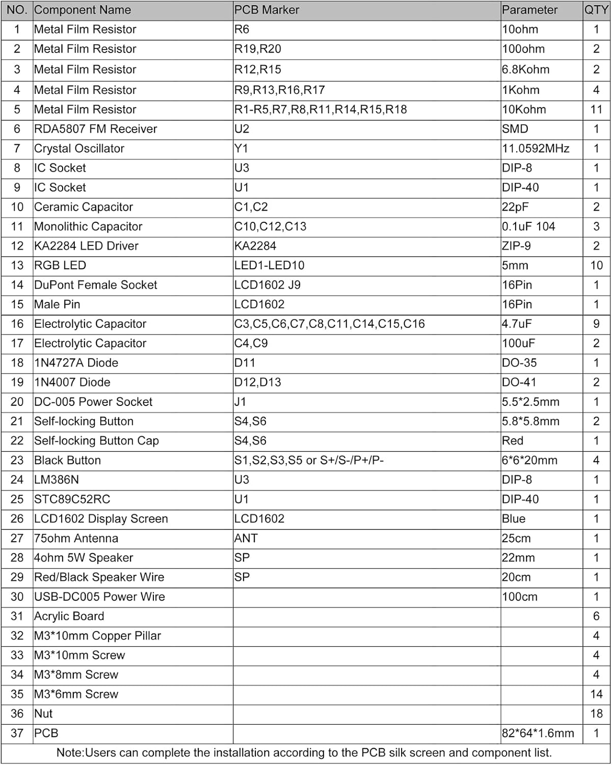
2.2-сүрөт: Detailed list of components with their corresponding PCB parameters and quantities. This table is crucial for identifying each part during assembly.
| ЖОК. | Компоненттин аталышы | PCB Parameter | САНЫ | |
|---|---|---|---|---|
| 1 | Металл тасма резистору | R19, R20 | 10 Ом | 2 |
| 2 | Металл тасма резистору | R1,R5-R7,R8,R11,R14,R15,R18 | 10Ком | 11 |
| 3 | Металл тасма резистору | R12, R15 | 6.8Ком | 2 |
| 4 | Металл тасма резистору | R9, R13, R16, R17 | 1Ком | 4 |
| 5 | RDA5807 FM кабыл алуучу | U2 | SMD | 1 |
| 6 | Crystal Oscillator | Y1 | 11.0592 МГц | 1 |
| 7 | IC Socket | U3 | Дип-8 | 1 |
| 8 | IC Socket | U1 | Дип-40 | 1 |
| 9 | Керамикалык конденсатор | C1,C2 | 22pF | 2 |
| 10 | Монолиттик конденсатор | C10,C12,C13 | 0.1 uF 104 | 3 |
| 11 | KA2284 LED драйвери | KA2284 | ZIP-9 | 2 |
| 12 | RGB LED | LED1-LED10 | 5мм | 10 |
| 13 | DuPont Аял розетка | LCD1602_J9 | 16Пин | 1 |
| 14 | Эркек Pin | 16Пин | 1 | |
| 15 | Электролиттик конденсатор | C3,C5,C6,C7,C8,C11,C14,C15,C16 | 4.7 uF | 9 |
| 16 | Электролиттик конденсатор | C4,C9 | 100 uF | 2 |
| 17 | 1N4727A Diode | D11 | DO-35 | 1 |
| 18 | 1N4007 диод | D12,D13 | DO-41 | 2 |
| 19 | DC-005 электр розетка | J1 | 5.5*2.5мм | 1 |
| 20 | Өзүн-өзү кулпулоо баскычы | S4, S6 | 5.8*5.8мм | 2 |
| 21 | Өзүн-өзү бекитүүчү баскыч капкагы | S4, S6 | Кызыл | 1 |
| 22 | Кара баскыч | S1,S2,S3,S5 же S+/S-/P+/P- | 6*6*20мм | 4 |
| 23 | LM386N | U3 | Дип-8 | 1 |
| 24 | STC89C52RC | U1 | Дип-40 | 1 |
| 25 | LCD1602 дисплей экраны | LCD1602 | Көк | 1 |
| 26 | 75 Ом антенна | ANT | 25см | 1 |
| 27 | 4 Ом 5 Вт динамик | SP | 22мм | 1 |
| 28 | Кызыл/Кара динамик зымы | SP | 20см | 1 |
| 29 | USB-DC005 электр зымы | 100см | 1 | |
| 30 | Акрил тактасы | 6 | ||
| 31 | M3*10mm Жез мамы | 4 | ||
| 32 | M3*10mm Бурама | 4 | ||
| 33 | M3*8mm Бурама | 4 | ||
| 34 | M3*6mm Бурама | 14 | ||
| 35 | Жаңгак | 18 | ||
| 36 | PCB | 82*64*1.6мм | 1 |
Эскертүү: Колдонуучулар PCB жибек экранына жана компоненттеринин тизмесине ылайык орнотууну аягына чыгара алышат.
3. Монтаждоо боюнча нускамалар
Баштоодон мурун
- Керектүү куралдар: Soldering iron, solder, wire cutters, small screwdriver set.
- Компоненттин идентификациясы: Carefully identify each component using the provided component list and the PCB silk screen.
- Полярдуулук: Pay close attention to the polarity of diodes, electrolytic capacitors, and LEDs. Incorrect polarity can damage components.
- SMD Component: The RDA5807 FM Receiver (U2) is a Surface Mount Device (SMD). It needs to be carefully placed on the PCB and then fixed.
- LED орнотуу: User must install the LED according to the specified rules (polarity and orientation). Otherwise, some LEDs will not light.
PCB Layout and Schematic
Familiarize yourself with the PCB layout and schematic diagram before soldering. This will help in understanding component placement and circuit flow.
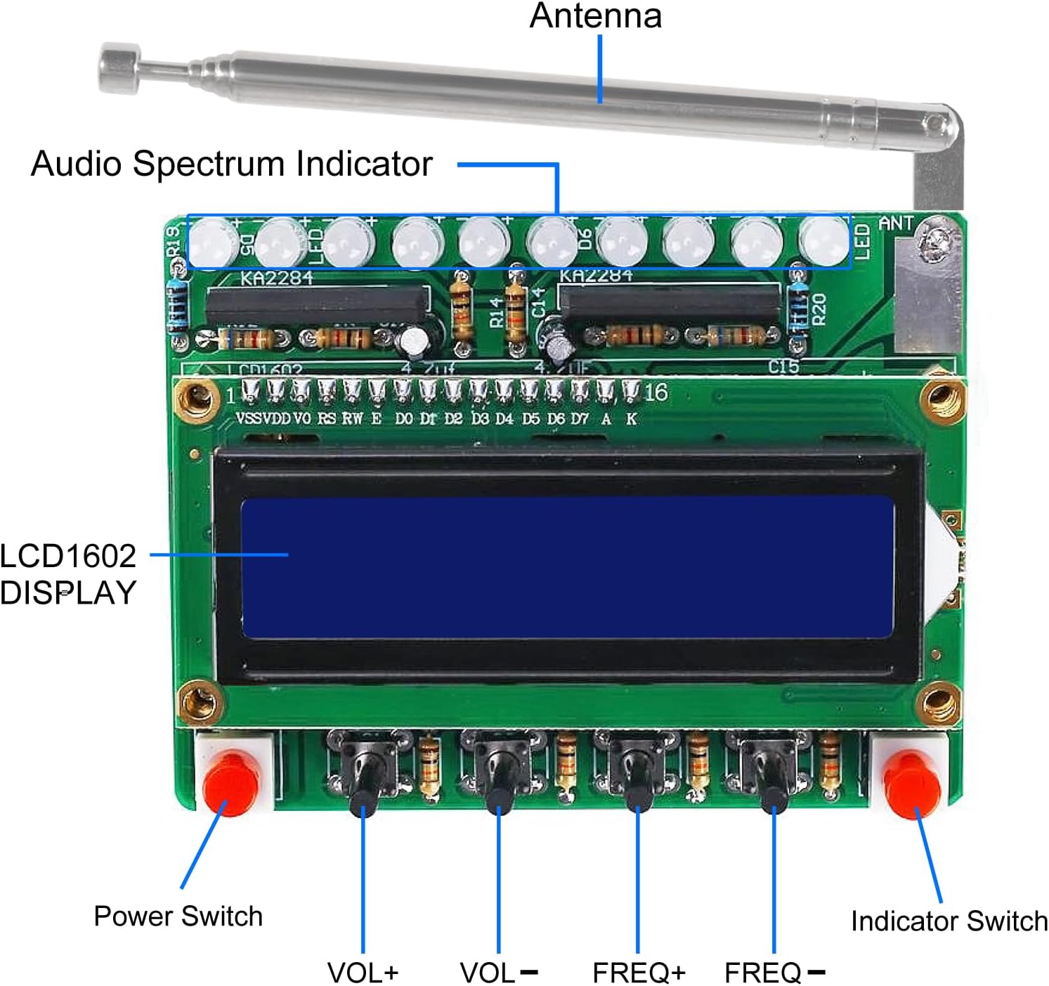
3.1-сүрөт: Labeled components on the assembled PCB, indicating the location of the antenna, audio spectrum indicator, LCD display, and control buttons.

3.2-сүрөт: Detailed schematic diagram illustrating the electronic connections and circuit design of the FM radio receiver.
Кадамдык Ассамблея
- Prepare the PCB: Ensure the PCB is clean and free of any debris.
- Ширетүүчү резисторлор: Start by soldering all metal film resistors (R1-R20) to their designated spots on the PCB. Resistors are not polarized.
- Solder Diodes: Solder the 1N4727A (D11) and 1N4007 (D12, D13) diodes. Ensure correct polarity; the band on the diode matches the band on the PCB silk screen.
- Solder Ceramic and Monolithic Capacitors: Solder C1, C2, C10, C12, C13. These are non-polarized.
- Solder IC Sockets: Solder the DIP-8 (U3) and DIP-40 (U1) IC sockets. Ensure the notch on the socket aligns with the notch on the PCB silk screen.
- Solder Crystal Oscillator: Solder Y1 (11.0592MHz) to its position.
- Solder Electrolytic Capacitors: Solder C3, C4, C5, C6, C7, C8, C9, C11, C14, C15, C16. These are polarized; ensure the longer lead (positive) goes into the '+' hole or the marked side on the PCB.
- Ширетүүчү LEDдер: Solder the 10 RGB LEDs (LED1-LED10). Pay close attention to their polarity and orientation as specified in the component list and PCB markings.
- Solder KA2284 LED Drivers: Solder the two KA2284 (ZIP-9) LED drivers.
- Solder Buttons and Power Socket: Solder the self-locking buttons (S4, S6), black buttons (S1, S2, S3, S5), and the DC-005 power socket (J1).
- Solder Speaker and Speaker Wire: Solder the 4ohm 5W speaker to the PCB using the red/black speaker wire. Ensure correct polarity if marked.
- Интегралдык микросхемаларды орнотуу: Carefully insert the LM386N (U3) and STC89C52RC (U1) ICs into their respective sockets, aligning the notch on the IC with the notch on the socket.
- Connect LCD1602 Display: Solder the 16-pin male header to the LCD1602 display. Then, connect the LCD1602 display to the DuPont Female Socket (LCD1602_J9) on the PCB.
- Assemble Acrylic Casing: Follow the acrylic board shapes to assemble the protective casing around the PCB using the M3 copper pillars, screws, and nuts. Ensure the PCB fits securely within the casing.
- Антеннаны тиркөө: Connect the 75ohm antenna to the designated ANT port on the PCB.
- Акыркы текшерүү: Before powering on, visually inspect all solder joints for shorts or cold joints. Double-check component placement and polarity.
4. Иштөө нускамалары
Once assembled, your FM Radio Receiver DIY Kit is ready for operation. Connect the USB-DC005 power wire to the power socket (J1) and a 4.5V~5.5V DC power source.

4.1-сүрөт: The assembled FM Radio Receiver in operation, demonstrating its LCD display and integrated LED lights.
Негизги башкаруу элементтери
- Left Button (Power Switch): Press to turn the power supply ON or OFF.
- Right Button (Indicator Switch): Press to turn the RGB spectrum indicator flashing ON or OFF.
- S+ / S- Buttons (Volume Adjustment): Press S+ to increase volume, and S- to decrease volume.
- P+ / P- Buttons (Frequency Adjustment): Press P+ to increase the receiving frequency, and P- to decrease the receiving frequency. This allows you to tune into different FM stations.
5. Техникалык шарттар
| Өзгөчөлүк | Спецификация |
|---|---|
| Work Voltage | DC 4.5V ~ 5.5V |
| Чыгуу импедансы | 4 Ом |
| Чыгуу күчү | 5W |
| Output Channel | Моно |
| Receiver Frequency | 87.0MHz ~ 108.0MHz |
| Frequency тактыгы | 0.1 МГц |
| Эквиваленттүү ызы-чуу | >= 30дБ |
| Иш температурасы | -40℃ ~ 85℃ |
| Жумуштун нымдуулугу | 5% ~ 95% RH |
| Дисплей түрү | LCD1602 |
| Элемент Салмагы | 0.48 унция |
| Пакеттин өлчөмдөрү | 3.2 x 1.1 x 0.2 дюйм |
6. Кыйынчылыктарды
If you encounter issues with your FM Radio Receiver DIY Kit, please refer to the following common problems and solutions:
- No Power / Display Off:
- Ensure the power supply is connected correctly (DC 4.5V~5.5V).
- Check the power switch (left button) is in the ON position.
- Verify all power connections and solder joints on the PCB.
- Confirm the polarity of electrolytic capacitors and diodes.
- No Sound / Weak Sound:
- Check speaker connections and ensure the speaker is functional.
- Adjust the volume using the S+ / S- buttons.
- Ensure the LM386N (U3) IC is correctly inserted into its socket.
- Verify solder joints for the speaker and audio output components.
- Poor FM Reception / Static:
- Антеннаны толугу менен узартыңыз.
- Adjust the frequency using the P+ / P- buttons to find a clear station.
- Avoid using the radio in environments with strong signal interference. This is a wireless module and can be affected by external noise.
- Ensure the RDA5807 FM Receiver (U2) is properly placed and fixed.
- LEDs Not Lighting / Incorrectly Flashing:
- Verify the installation direction and polarity of each RGB LED. Incorrect orientation will prevent them from lighting.
- Check the solder joints for all LEDs and the KA2284 LED drivers.
- Ensure the right button (Indicator Switch) is ON.
- LCD Display Issues (Blank / Garbled Text):
- Ensure the LCD1602 display is correctly connected to the DuPont Female Socket.
- Verify all 16 pins are making good contact.
- Check the solder joints for the LCD connector on the PCB.
- General Assembly Issues:
- Review all solder joints for cold joints (dull, grainy appearance) or solder bridges (short circuits).
- Ensure all components are in their correct positions as per the PCB silk screen and schematic.
- Double-check the polarity of all polarized components.
7. Техникалык тейлөө
To ensure the longevity and proper functioning of your FM Radio Receiver DIY Kit, follow these maintenance guidelines:
- Тазалоо: Use a soft, dry cloth to clean the exterior of the radio. Avoid using liquid cleaners or solvents, which can damage the acrylic casing же электрондук компоненттер.
- Сактагыч: Радиону салкын, кургак жерде, түз күн тийбеген, өтө температура жана жогорку нымдуулуктан алыс жерде сактаңыз.
- Колдонуу: Handle the assembled radio with care to avoid dropping it or subjecting it to strong impacts, which could dislodge components or crack the casing.
- Электр камсыздоо: Always use a stable DC 4.5V~5.5V power supply. Using an incorrect voltage can damage the circuit.
8. Кепилдик жана колдоо
Specific warranty information for this DIY kit is not provided in the product details. As a DIY kit, its functionality largely depends on the user's assembly process.
For any questions regarding installation instructions, component identification, or technical support, please contact the manufacturer, DORHEA, directly via email. They can provide further assistance and guidance for your project.
For general inquiries or to visit the DORHEA store, you may refer to their official Amazon store page: Visit the DORHEA Store
Ask a question about this manual
Ask about setup, troubleshooting, compatibility, parts, safety, or missing instructions. Manuals+ will review the question and use this page’s manual context to help answer it.