1. Киришүү
This manual provides detailed instructions for the installation, operation, and maintenance of the eletechsup 24V 20A Brushed Motor Overload Overcurrent Short Circuit Protector. This device is designed to protect brushed DC motors from damage due to overload, overcurrent, and short circuits, while also providing forward and reverse control capabilities.
2. Коопсуздук чаралары
- Always disconnect power before making any connections or adjustments to the module.
- туура томду камсыз кылууtage and current ratings are observed to prevent damage to the module or connected components.
- Avoid touching the circuit board when power is applied.
- Install the module in a dry, well-ventilated area, away from flammable materials.
- If you are unsure about any step, consult a qualified electrician or technician.
3. Продукциянын өзгөчөлүктөрү
- Applicable to 12V/24V Brushed DC motors.
- Provides motor control for both forward and reverse directions.
- Features two selectable working modes: Non-locking (Momentary) and Self-locking.
- Adjustable overload current protection range.
- Integrated overload, overcurrent, and short circuit protection.
4. Technical Specifications (24V 20A Version)
- Working Voltage: DC 24V (DC power supply power ≥ motor power x3)
- Applicable Motor: 24V Brushed DC motor
- Максималдуу ток: Short-term working current 20A, long-term working current 10A
- Protection Current Adjustment Range: 0.2A ~ 20A
- Мотор башкаруу: Алга, Артка
- Иштөө режимдери: Non-locking (Momentary) and Self-locking
- Working Current (excluding motor): 5-70мА
- Өлчөмү: 87мм x 58мм x 25мм
- Салмагы: 80.1 грамм
5. Pinout Diagram and Description
Refer to the diagram below for the pin assignments and their functions.

| Pin | Description |
|---|---|
| M- | Motor Negative Terminal |
| M+ | Motor Positive Terminal |
| VCC | Power Supply Positive Terminal |
| GND | Power Supply Negative Terminal |
| COM | Control Signal Common Terminal (Connect to GND) |
| FWD | Forward Control Input |
| REV | Reverse Control Input |
| LED | Power Supply Indicator (LED) |
| OL | Overload Signal Output |
| РЕЖИМ | Momentary/Self-locking Mode Selection Jumper |
| ADJ | Overload Current Regulation Potentiometer |
6. Орнотуу боюнча колдонмо
6.1 Wiring the Power Supply and Motor
Connect the DC power supply and the brushed DC motor as shown in the diagram below. Ensure correct polarity for both the power supply and the motor.
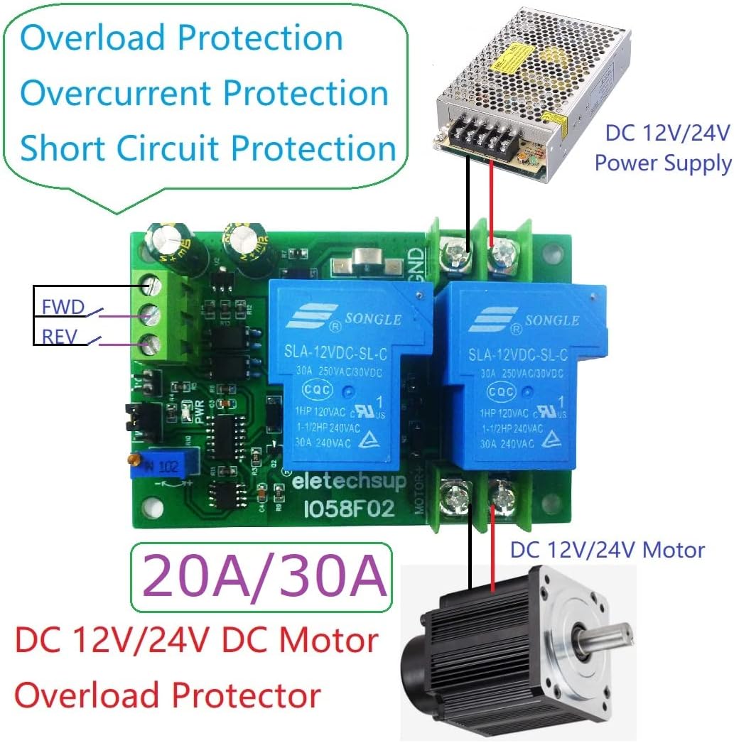
- Connect the positive terminal of your DC 24V power supply to the VCC terminal on the module.
- Connect the negative terminal of your DC 24V power supply to the GND terminal on the module.
- Connect the positive terminal of your brushed DC motor to the M+ terminal on the module.
- Connect the negative terminal of your brushed DC motor to the M- terminal on the module.
6.2 Wiring Control Signals
Control the motor's direction using external buttons or an MCU/PLC connected to the FWD and REV inputs.

- Connect the common terminal of your control buttons or MCU/PLC to the COM terminal on the module (which should be connected to GND).
- Connect a button or control signal for forward movement to the FWD терминал.
- Connect a button or control signal for reverse movement to the REV терминал.
7. Иштөө нускамалары
7.1 Working Modes Selection
The module supports two working modes, selected via the РЕЖИМ jumper:
- Non-locking (Momentary) Mode: When the FWD or REV input is activated (e.g., button pressed), the motor runs in the corresponding direction. The motor stops when the input is released.
- Өзүн-өзү кулпулоо режими: When the FWD or REV input is briefly activated, the motor starts running in the corresponding direction and continues until the same input is activated again, or the other direction's input is activated.
Adjust the MODE jumper according to your application requirements.
7.2 Алдыга/Артка башкаруу
- To run the motor in the forward direction, activate the FWD киргизүү.
- To run the motor in the reverse direction, activate the REV киргизүү.
- Ensure only one direction input is active at a time to prevent conflicts.
8. Adjusting Overload Protection
The overload protection current can be adjusted using the ADJ potentiometer on the board. This allows you to set the maximum current the motor can draw before the protection circuit activates.
- Use a small screwdriver to carefully turn the ADJ потенциометр.
- Turning clockwise typically increases the protection current threshold.
- Turning counter-clockwise typically decreases the protection current threshold.
- It is recommended to set the protection current slightly above the motor's normal operating current under load to prevent nuisance tripping, but below the motor's stall current or maximum safe current.
9. Тиркемелер
This module is suitable for various applications requiring motor protection and directional control, including:
- Мотордун ашыкча жүктөлүшүнөн коргоо
- Мотордун ашыкча ток коргоо
- Motor Short Circuit Protection
- LED Overcurrent Protection (for specific LED drive circuits)
10. Кыйынчылыктарды
| Көйгөй | Мүмкүн себеп | Чечим |
|---|---|---|
| Мотор иштебейт. | No power, incorrect wiring, protection tripped. | Check power supply connections (VCC, GND). Verify motor connections (M+, M-). Ensure control signals (FWD/REV) are correctly applied. Check if overload protection has tripped (O.L indicator). |
| Motor runs in wrong direction. | Incorrect motor polarity or control signal. | Reverse M+ and M- connections to the motor. Verify FWD/REV control signals. |
| Protection trips too frequently. | Overload current set too low, motor drawing excessive current. | Increase the overload current threshold using the ADJ potentiometer. Check motor for mechanical issues or excessive load. |
| Protection does not trip. | Overload current set too high, module fault. | Decrease the overload current threshold using the ADJ potentiometer. Ensure the motor current exceeds the set threshold during an overload condition. |
11. Техникалык тейлөө
- Модулду чаңдан жана таштандыдан таза жана таза кармаңыз.
- Бардык туташуулардын коопсуз жана коррозия жок экендигин текшериңиз.
- Periodically inspect the board for any signs of damage or overheating.
- Do not expose the module to moisture or extreme temperatures.
12. Кепилдик жана колдоо
Кепилдик маалыматы же техникалык колдоо алуу үчүн сатуучуга же өндүрүүчүгө түздөн-түз кайрылыңыз. Сатып алганыңыздын далили катары сатып алуу дүмүрчөгүңүздү сактаңыз.