DEWIN RDABCRYRA-GS99825
DEWIN 2.2KW 220V Variable Frequency Drive (VFD) Inverter User Manual
Model: RDABCRYRA-GS99825
1. Киришүү
This manual provides essential information for the safe and efficient operation of your DEWIN 2.2KW 220V Single-Phase Input, Three-Phase Output Variable Frequency Drive (VFD) Inverter. Please read this manual thoroughly before installation, operation, or maintenance to ensure proper usage and to prevent damage to the equipment or injury to personnel.
The DEWIN VFD is designed to control the speed and torque of three-phase asynchronous motors, offering precise control and energy efficiency for various industrial applications.
2. Коопсуздук маалыматы
WARNING: Electrical shock hazard. Only qualified personnel should perform installation, wiring, and maintenance.
- Always disconnect power before performing any work on the VFD or connected equipment.
- Ensure proper grounding of the VFD and motor.
- Do not touch electrical components immediately after power disconnection, as residual voltage may be present. Wait at least 10 minutes for capacitors to discharge.
- Киргизилген томtage matches the VFD's specifications.
- VFDди нымдуулуктан, чаңдан жана дат басуучу газдардан коргоңуз.
- Do not operate the VFD with damaged cables or components.
3. Негизги өзгөчөлүктөрү
- Multiple Control Algorithms: Supports VF control for induction motors, open-loop magnetic flux vector control, standard open-loop control for permanent magnet synchronous motors, and open-loop vector control. Provides 150% starting torque at 0.5 Hz (sensorless vector control) for high torque, high precision, and wide speed control range.
- Rapid Current Limiting Function: Prevents frequent overcurrent alarms by quickly limiting current within a protected range during sudden load peaks or disturbances.
- Torque Limiting Function: Limits torque within a preset maximum range if the reference torque value exceeds the machine's maximum loadable torque, ensuring optimal system protection and mechanical efficiency.
- Independent Cooling Channel: Features a robust cooling fan and independent air duct design for efficient heat dissipation and low noise, ensuring long-term stable operation.
- Колдонуучуга ыңгайлуу дизайн: Compact size and a removable front panel facilitate easy installation, operation, and wiring. Screw terminals provide convenient cable connections.

Figure 3.1: DEWIN VFD Inverter highlighting features such as motor protection, energy saving, frequency control, and strong security.
4. Техникалык шарттар
| Параметр | Нарк |
|---|---|
| Модель номери | RDABCRYRA-GS99825 |
| Колдонулуучу мотордун кубаттуулугу | 2.2КВт |
| Input Rated Voltage | Бир фазалуу 220V |
| Киргизүү номиналдык жыштыгы | 50/60 Гц |
| Чыгуу Рейтинг Томtage | Үч фазалуу 220V |
| Output Frequency (Low Frequency Mode) | 0-320 Гц |
| Номиналдуу чыгаруу ток | 10A |
| Материал | Өрткө каршы ABS пластик |
| Орнотуу ыкмасы | Дубалга орнотулган |
| Коргоо деңгээли | IP20 |
| Муздатуу ыкмасы | Муздатуу желдеткич |
| Элемент Салмагы | 830 г |
| Пакеттин өлчөмдөрү | 19 x 17 x 11 см |

Figure 4.1: Physical dimensions and a summary of technical specifications for the DEWIN VFD Inverter.
5. Орнотуу
5.1 Физикалык орнотуу
The DEWIN VFD is designed for wall-mounted installation. Ensure the mounting surface is stable and capable of supporting the unit's weight. Allow adequate clearance around the VFD for proper ventilation, especially for the cooling fan.

5.1-сүрөт: Арткы view of the DEWIN VFD Inverter, showing the cooling fan and model information (Model: MS500-2S-2.2G, Power: 2.2KW, Input: 1PH AC220V 50/60Hz, Output: 3PH AC220V 0-320Hz 10A, Serial: JLS0022B21GB25080435).

5.2-сүрөт: Төмөнкү view of the DEWIN VFD Inverter, showing connection points.
5.2 Электр зымдары боюнча нускамалар
Refer to the following diagrams for correct wiring of the VFD. Incorrect wiring can lead to equipment damage or safety hazards.

Figure 5.3: Wiring diagram for connecting a single-phase 220V power supply to the VFD and a three-phase motor. Ensure the ground wire is properly connected.

Figure 5.4: Detailed basic operation wiring diagram, including connections for breaker, power input (R, S(L1), T(L2)), multi-function input terminals (X1-X4, GND), external keyboard interface (J10), potentiometer (5K, 10K, 10V, A1, GND), analog output (AO1, GND), RS485 communication (485+, 485-), relay output (TA, TC), and three-phase asynchronous motor (U, V, W, Ground).
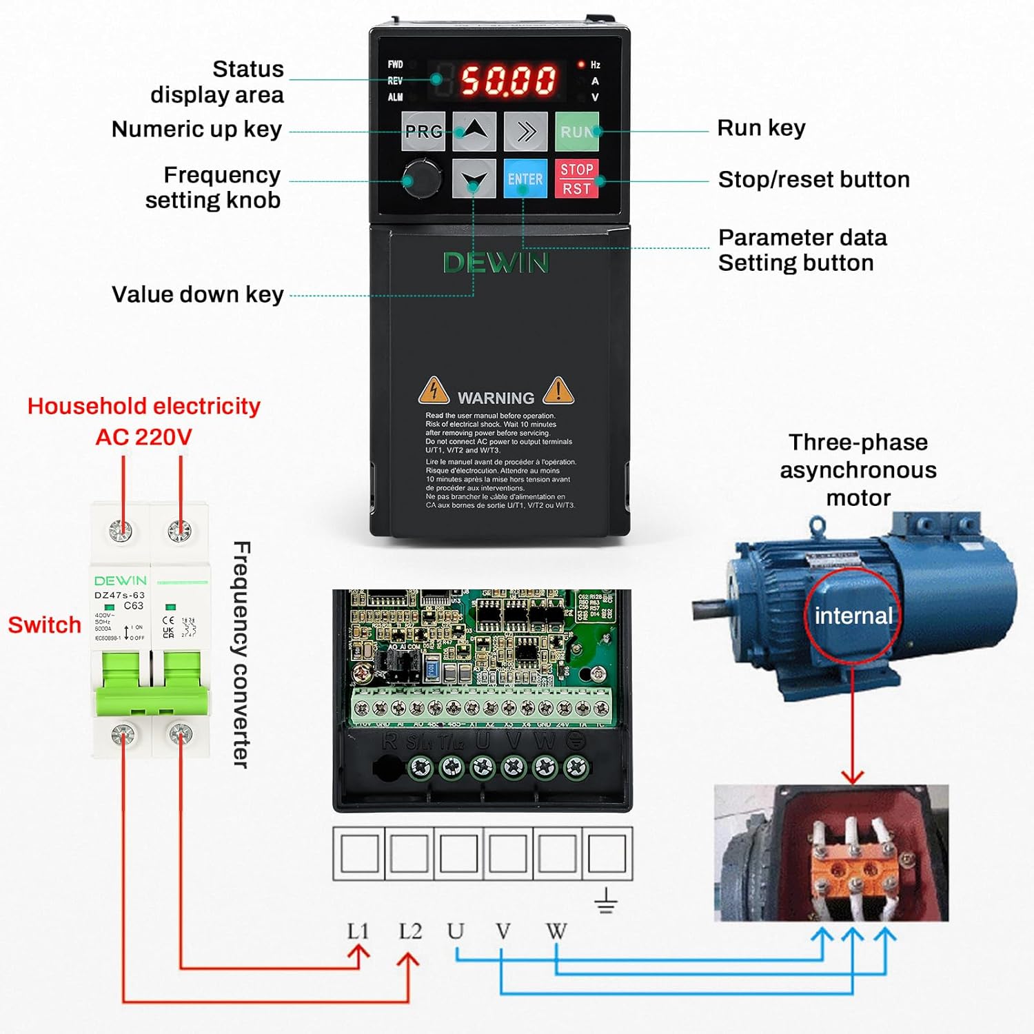
Figure 5.5: ашыкview showing the VFD control panel, connection to household AC 220V electricity via a switch, and wiring to a three-phase asynchronous motor.
6. Иштөө нускамалары
6.1 Башкаруу панелинин үстүнөview
The VFD features an intuitive control panel for easy operation and parameter setting.

6.1-сүрөт: Детальдуу view of the VFD control panel, indicating the status display area, numeric up/down keys, frequency setting knob, parameter data setting button (PRG), run key (RUN), and stop/reset button (STOP/RST).
- Status Display Area: Shows current operating frequency, voltage, current, and other status indicators.
- PRG (Program) Button: Used to enter parameter setting mode and navigate through menus.
- Өйдө/төмөн жебелер: Used to adjust values or navigate menu options.
- ENTER баскычы: Confirms selections or parameter changes.
- RUN баскычы: Моторду иштетет.
- STOP/RST Button: Stops the motor and resets any active alarms.
- Frequency Setting Knob: Allows for manual adjustment of the output frequency.
6.2 Негизги операциялардын ырааттуулугу
- Күйгүзүү: Ensure all wiring is correct and secure. Apply single-phase 220V power to the VFD. The display will illuminate.
- Жыштык коюу: Use the frequency setting knob or the Up/Down arrow keys to set the desired operating frequency.
- Моторду ишке киргизүү: басыңыз RUN моторду иштетүү үчүн баскычты басыңыз. VFD иштейтamp up to the set frequency.
- Моторду токтотуу: басыңыз STOP/RST моторду токтотуу үчүн баскычты басыңыз. VFD күйгүзүлөтamp down and stop.
- Параметрди тууралоо: басыңыз PRG button to enter the parameter setting menu. Use the Up/Down arrows to navigate and ENTER to select and confirm. Refer to the detailed parameter manual (if provided separately) for advanced settings.
7. Техникалык тейлөө
Regular maintenance ensures the longevity and reliable operation of your VFD.
- Тазалоо: Periodically clean the VFD's exterior and cooling fan vents to prevent dust accumulation, which can hinder heat dissipation. Use a soft, dry cloth. Do not use liquid cleaners.
- Текшерүү: Regularly inspect all wiring connections for tightness and signs of wear or damage. Check for any unusual noises or odors during operation.
- Курчап турган чөйрө: Ensure the operating environment remains within specified temperature and humidity ranges. Avoid exposure to direct sunlight, excessive vibration, or corrosive substances.
- Fan Check: Verify that the cooling fan is operating freely and without obstruction.
For any internal maintenance or repairs, contact qualified service personnel.
8. Кыйынчылыктарды
This section addresses common issues you might encounter with the VFD. For complex problems, consult a qualified technician.
8.1 Жалпы маселелер жана чечимдер
| Көйгөй | Мүмкүн себеп | Чечим |
|---|---|---|
| VFD does not power on. | Киргизүү кубаты жок; туура эмес зымдар; ички бузук. | Check power supply and circuit breaker. Verify input wiring. If problem persists, contact support. |
| Мотор иштебейт. | Incorrect frequency setting; motor wiring error; VFD in fault state; parameter misconfiguration. | Check frequency setting. Verify motor wiring (U, V, W). Check VFD display for error codes and reset if necessary. Review параметр орнотуулары. |
| Overcurrent alarm (OC). | Sudden load increase; short circuit in motor or wiring; acceleration time too short. | Reduce load. Check motor and wiring for shorts. Increase acceleration time parameter. Utilize the rapid current limiting function. |
| Overvoltage alarm (OV). | Киргизүү тtage too high; deceleration time too short; regenerative load. | Киргизүүнү текшерүү томtage. Increase deceleration time parameter. Consider adding a braking resistor for regenerative loads. |
| Overheat alarm (OH). | Insufficient ventilation; ambient temperature too high; cooling fan malfunction. | Ensure proper ventilation and clear fan vents. Reduce ambient temperature. Check cooling fan operation. |
If you encounter an issue not listed here or cannot resolve a problem, please contact DEWIN customer support.
9. Кардарларды колдоо кызматы
For technical assistance, warranty information, or service inquiries, please contact DEWIN customer support through the retailer where the product was purchased or visit the official DEWIN webсайт.
When contacting support, please have your model number (RDABCRYRA-GS99825) and purchase date available.
Ask a question about this manual
Ask about setup, troubleshooting, compatibility, parts, safety, or missing instructions. Manuals+ will review the question and use this page’s manual context to help answer it.