Introduction
The System Sensor HR-LF is a low frequency sounder designed for indoor use in security and surveillance systems, specifically for sound detection and alarm output. This device is engineered to provide clear and effective audible alerts, crucial for life safety applications. This manual provides essential information for the proper installation, operation, and maintenance of your HR-LF sounder.
Коопсуздук маалыматы
Please read and understand all instructions before installing or operating the HR-LF sounder. Failure to follow these instructions may result in property damage, injury, or death. This device must be installed by qualified personnel in accordance with all local and national electrical and fire codes.
- Кубатты өчүрүү: Always disconnect power to the circuit before installing, servicing, or removing the device.
- Туура зымдар: Ensure all wiring connections are secure and comply with the wiring diagram provided with the device.
- Экологиялык шарттар: Install the device in an environment that meets its specified operating conditions.
- Сыноо: Regularly test the device after installation and during routine maintenance to ensure proper operation.
Пакеттин мазмуну
Орнотууну баштоодон мурун бардык элементтердин бар экенин текшериңиз:
- System Sensor HR-LF Low Frequency Sounder (Red)
- Монтаждоочу жабдуулар (буроолор, анкерлер)
- Орнотуу боюнча колдонмо (бул документ)
Орнотуу жана орнотуу
The HR-LF sounder is designed for surface mount installation. Follow these steps for proper setup:
- Жайгашкан жерди тандоо: Select an indoor location that provides optimal sound coverage and complies with local codes. Ensure the mounting surface is flat and secure.
- Зымдарды даярдоо: Route the necessary electrical wiring to the chosen mounting location. Ensure power is disconnected before proceeding.
- Монтаждоо:
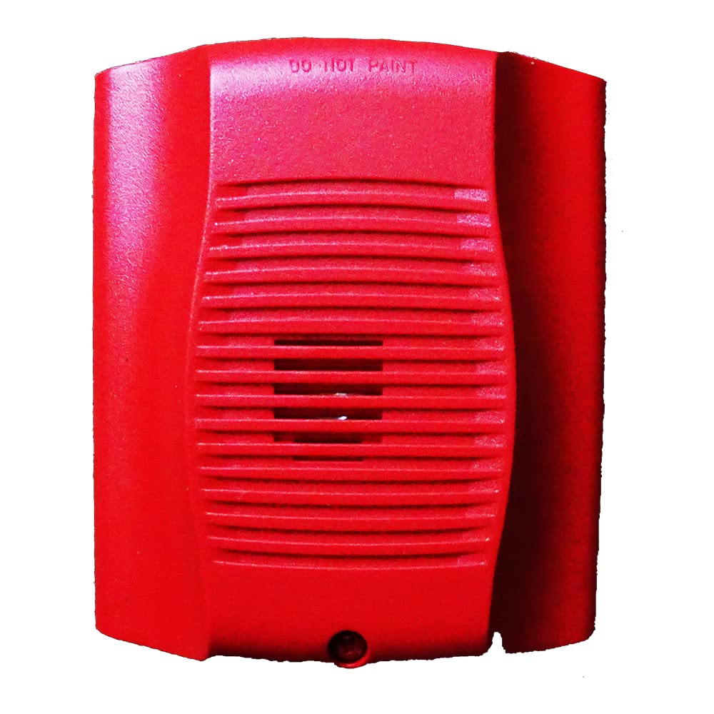
Сүрөт: алдыңкы view of the System Sensor HR-LF low frequency sounder. This red device features a grille for sound emission and mounting points for surface installation.
- Position the sounder base against the wall or ceiling at the desired mounting point.
- Mark the locations for the mounting screws.
- Drill pilot holes if necessary, and insert wall anchors if mounting into drywall.
- Secure the sounder base to the mounting surface using the provided screws.
- Зымдарды туташтыруу: Connect the field wiring to the terminal block on the sounder base according to the wiring diagram provided with the device. Pay close attention to polarity.
- Attach Sounder Head: Once wiring is complete and secure, attach the sounder head to the mounted base, ensuring it locks into place.
- Күчтү калыбына келтирүү: Бардык туташууларды текшергенден кийин, чынжырдын кубатын калыбына келтириңиз.
- Сыноо операциясы: Perform an operational test as described in the "Operating Instructions" section.
Иштөө нускамалары
The System Sensor HR-LF low frequency sounder operates as an alarm output device, typically activated by a connected fire alarm control panel or security system. It is designed to produce a distinct low-frequency tone for occupant notification.
- Жандандыруу: The sounder will activate when it receives a signal from the connected control panel, indicating an alarm condition.
- Sound Pattern: The HR-LF typically produces a temporal 3 pattern (three short pulses followed by a pause), which is standard for fire alarm notification. Refer to your control panel's documentation for specific output patterns.
- Өчүрүү: The sounder will deactivate when the alarm condition on the control panel is cleared or reset.
Note: The HR-LF is an output device and does not have user-configurable settings directly on the unit. All operational parameters are controlled by the connected fire alarm or security system.
Техникалык тейлөө
Regular maintenance ensures the continued reliable operation of your HR-LF sounder.
- Тазалоо: Periodically clean the exterior of the sounder with a soft, dry cloth to remove dust and debris. Do not use abrasive cleaners or solvents.
- Сыноо: Conduct periodic functional tests in accordance with local codes and manufacturer recommendations (typically annually) to ensure the sounder activates and produces the correct sound pattern.
- Текшерүү: Visually inspect the device for any signs of damage, loose connections, or obstructions to the sound output.
Проблемаларды чечүү
If your HR-LF sounder is not functioning as expected, refer to the following common issues and solutions:
| Көйгөй | Мүмкүн себеп | Чечим |
|---|---|---|
| Sounder does not activate. | Аппаратка кубат жок. Туура эмес зым. Control panel not sending activation signal. | Электр менен камсыздоону текшерүү. Check wiring connections against diagram. Inspect control panel status and output. |
| Sounder activates intermittently. | Бошогон зымдар байланышы. Faulty control panel output. | Бардык зым туташууларын бекитиңиз. Consult control panel manual or contact qualified technician. |
| Үн алсыз же бурмаланган. | Obstruction in front of sounder. Аппараттын бузулушу. | Бардык тоскоолдуктарды тазалаңыз. физикалык зыянды текшерүү; зарыл болсо алмаштыруу. |
If troubleshooting steps do not resolve the issue, contact System Sensor technical support or a qualified service technician.
Техникалык шарттар
| Бренд | Системалык сенсор |
| Модель номери | HR-LF |
| Материал | Пластик |
| Стиль | Заманбап |
| Монтаж түрү | Surface Mount |
| Output Type | Ойготкуч |
| Өзгөчө колдонуулар | Indoor, Sound Detection |
| ASIN | B015NEAOB2 |
| Дата биринчи жеткиликтүү | 5-октябрь, 2016-жыл |
Кепилдик жана колдоо
System Sensor products are designed for reliability and performance. For specific warranty information, please refer to the warranty statement included with your product packaging or visit the official System Sensor website. For technical support, installation assistance, or service inquiries, please contact System Sensor customer service or your authorized distributor.
Байланыш маалыматы, адатта, өндүрүүчүнүн сайтынан тапса болот webсайт же продукт таңгак.


