Introduction
This manual provides comprehensive instructions for the safe and efficient operation of your Adastra Induction Loop Amplifier LA-300 mkII. Please read this manual thoroughly before use and retain it for future reference.
The Adastra LA-300 mkII is an induction amplifier designed to drive a cable loop, providing assisted listening for hearing aid users in public and commercial buildings. It is suitable for hearing aids fitted with a "T" switch.
Коопсуздук нускамалары
- Электр камсыздоо: Ensure the correct power supply (110/240Vac, 50/60Hz) is used as specified. Disconnect from mains before cleaning or servicing.
- Вентиляция: Вентиляция тешиктерин жаап албаңыз. Ашыкча ысып кетүүнүн алдын алуу үчүн аппараттын айланасында адекваттуу аба агымын камсыз кылыңыз.
- Нымдуулук: Аппаратты жамгыр же нымдуулукка дуушар кылбаңыз. Аппараттын үстүнө вазалар сыяктуу суюктуктар толтурулган буюмдарды койбоңуз.
- Тейлөө: Бардык тейлөө иштерин квалификациялуу тейлөө кызматкерлерине тапшырыңыз. Түзмөктү өз алдынча оңдоого аракет кылбаңыз.
- Жайгашкан жери: Түзмөктү туруктуу, тегиз жерге коюңуз. Аны жылуулук булактарынын жанына же күн нуру түз тийген жерге койбоңуз.
- Loop Cable: Ensure the induction loop cable is installed correctly and safely to avoid tripping hazards.
Пакеттин мазмуну
Please check the contents of the packaging to ensure all items are present and in good condition.
- Адастра индукциялык цикли Amplifier LA-300 mkII
- IEC Mains Power Cable
- Колдонуучунун Колдонмосу (бул документ)

Image: The Adastra LA-300 mkII Induction Loop Amplifier as packaged in its brown cardboard box, indicating the model name and "300m² max. area coverage".
Продукт өзгөчөлүктөрү
The Adastra LA-300 mkII Induction Loop Amplifier төмөнкү негизги функцияларды сунуштайт:
- Suitable for hearing aids fitted with a "T" switch.
- Mic/line level switch for each input.
- Phantom power switch for each input.
- Tamper proof channel volume, bass & treble and loop current level controls.
- Adjustable metal loss correction.
- Alarm contacts for built-in siren.
- Priority switchable for channel 1.
- Peak current LED indication.
- 19" rack mountable design.
Башкаруу каражаттары жана байланыштар
Front Panel
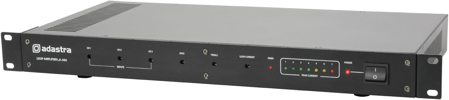
Image: Front panel of the Adastra LA-300 mkII amplifier, showing input level controls (CH1, CH2, CH3), Bass, Treble, Loop Current, Siren, Peak Current LEDs, and Power switch.
- CH1, CH2, CH3 Input Level Controls: Adjusts the input sensitivity for each channel. These are tamper-proof and require a screwdriver.
- Басс башкаруу: Adjusts the low-frequency response. Tampэр-далил.
- Үч ыргак башкаруу: Adjusts the high-frequency response. Tampэр-далил.
- Loop Current Control: Adjusts the output current to the induction loop. Tampэр-далил.
- Siren LED: Indicates activation of the built-in siren (if connected to alarm contacts).
- Peak Current LEDs: A series of LEDs indicating the output current level to the loop, helping to prevent overload.
- Кубат которгучу: Түзмөктү күйгүзөт/өчүрөт.
Арткы панель

Image: Rear panel of the Adastra LA-300 mkII amplifier, showing the IEC power inlet, voltage selector, loop output/alarm contacts, and three input channels (XLR/RCA combo jacks) with associated switches, plus metal loss correction control.
- IEC Mains Inlet: туташтырат amplifier to the mains power supply using the provided IEC cable.
- Тtage Тандоочу: Switch to select between 110V and 240V operation. Ensure this is set correctly for your region.
- Loop Output / Alarm Contacts: Terminal block for connecting the induction loop cable and external alarm systems.
- CH1, CH2, CH3 Inputs: Combo XLR/RCA jacks for connecting audio sources. Each channel has associated switches for Mic/Line level and Phantom Power.
- Металл жоготууларын оңдоо: Rotary control to compensate for signal loss caused by metal structures in the building.
Жайгашуу
1. Induction Loop Installation
The induction loop cable should be installed around the perimeter of the area where assisted listening is required. Ensure the loop forms a complete circuit. Consult a professional for optimal loop design and installation for larger or complex areas.
- Connect the ends of the induction loop cable to the "LOOP OUTPUT" terminals on the rear panel.
- Ensure correct polarity if specified by your loop cable manufacturer.
2. Аудио киргизүү байланыштары
Connect your audio sources (microphones, line-level devices) to the CH1, CH2, or CH3 inputs on the rear panel.
- Use XLR connectors for microphones or balanced line-level signals.
- Use RCA connectors for unbalanced line-level signals.
- Set the Mic/Line switch for each channel according to the connected device.
- Activate Phantom Power if using condenser microphones that require it.
3. Power Connection
- Before connecting power, verify the Voltage Selector switch on the rear panel is set to the correct voltagсиздин аймагыңыз үчүн (110V же 240V).
- Connect the supplied IEC mains power cable to the IEC inlet on the rear panel and then to a suitable mains power outlet.
Иштөө нускамалары
1. Күйгүзүү
Press the Power switch on the front panel to turn on the unit. The Power LED will illuminate.
2. Initial Level Setting
Using a small flat-head screwdriver, carefully adjust the tamper-proof controls on the front panel:
- коюңуз CH1, CH2, CH3 Input Level Controls to a low setting initially.
- коюңуз Бас жана Үч эсе controls to their center (flat) position.
- коюңуз Loop Current Control төмөн орнотууга.
3. Үн деңгээлин жөндөө
Play an audio source through one of the connected inputs. Gradually increase the corresponding Input Level Control until the Peak Current LEDs begin to illuminate, indicating signal presence. Adjust the Loop Current Control to achieve the desired field strength within the loop area. The Peak Current LEDs should ideally fluctuate in the green/yellow range, occasionally touching red during peak audio levels.
Use the Bass and Treble controls to fine-tune the audio quality for clarity and intelligibility within the loop area.
4. Metal Loss Correction
If the installation environment contains significant metal structures (e.g., reinforced concrete, metal ceilings), these can cause frequency-dependent signal loss. Use the Metal Loss Correction control on the rear panel to compensate for this. Adjust it while monitoring the sound quality within the loop area to achieve a balanced frequency response.
5. Priority Function (Channel 1)
Channel 1 has a switchable priority function. When activated, audio on Channel 1 will automatically duck (reduce the volume of) audio on Channels 2 and 3, making Channel 1 the dominant source. This is useful for announcements or emergency messages.
Техникалык тейлөө
- Тазалоо: Disconnect the unit from the mains power. Use a soft, dry cloth to clean the exterior. Do not use abrasive cleaners or solvents.
- Вентиляция: Periodically check that the ventilation grilles are free from dust and debris to ensure proper cooling.
- Текшерүү: Regularly inspect all cables and connections for any signs of wear or damage.
- Сактагыч: If storing the unit for an extended period, ensure it is kept in a cool, dry place, away from direct sunlight and extreme temperatures.
Проблемаларды чечүү
| Көйгөй | Мүмкүн себеп | Чечим |
|---|---|---|
| Кубат жок / Бирдик күйбөйт |
|
|
| No audio output from loop |
|
|
| Distorted audio / Peak LEDs constantly red |
|
|
| Uneven frequency response in loop area |
|
|
Техникалык шарттар
| Параметр | Нарк |
|---|---|
| Электр камсыздоо | 110/240Vac, 50/60Гц (IEC) |
| Жыштык жооп | 50Гц - 5кГц (±3дБ) |
| Киргизүү сезгичтиги: сызык | -6дБу/6к Ом |
| Киргизүү сезгичтиги: микрофон | -56дБу/2к Ом |
| Сигнал ызы-чуу катышы | 75дБ (сап), 60дБ (микрофон) |
| THD | <1% |
| Рак бийиктиги | 1U |
| Аймакты камтуу | 300м² макс. |
| Өлчөмдөр | 483 x 235 x 44 мм |
| Салмагы | 4.22кг |
| Элементтин моделинин номери | 952.864UK |
Кепилдик жана колдоо
Adastra products are designed and manufactured to the highest standards. For warranty information and technical support, please refer to the warranty card included with your product or visit the official Adastra webсайт. Сураныч, кепилдик дооматтар үчүн сатып алуу далилиңизди сактап коюңуз.
For further assistance or troubleshooting not covered in this manual, please contact Adastra customer support or your local distributor.


