1. Киришүү
The SMARTGEN EP4300 Engine Controller is designed for the control and data display of engines, particularly electric-controlled engines. It facilitates engine start/stop, speed control, data measurement, and alarm display. Featuring a 4.3-inch color LCD, the controller supports both Chinese and English languages, offering reliability and ease of use.
Utilizing 32-bit microprocessor technology, the EP4300 ensures precise measurement of various parameters. Most parameters can be adjusted directly from the front panel, with all parameters also configurable via USB or RS485 ports using a PC. Its compact design, straightforward wiring, and high reliability make it suitable for diverse engine automation systems.
2. Негизги өзгөчөлүктөрү
- ARM-based 32-bit SCM for high hardware integration.
- 4.3-inch color LCD display with 480x272 resolution and adjustable backlight (automatic or manual).
- Supports selectable Chinese and English languages for convenient commissioning.
- Silicon panel and pushbuttons with hard screen acrylic for display protection.
- CANBUS port for communication with J1939 engines, enabling monitoring of data (e.g., water temperature, oil pressure, engine speed, fuel consumption) and engine start/stop control.
- Three programmable analog sensor inputs: Sensor 3 supports resistance, voltage, or current sensors, while other sensor inputs are for resistance sensors only.
3. Продукт бүтүп калдыview
3.1 алдыңкы панели
The front panel of the EP4300 features a 4.3-inch color LCD for displaying engine parameters and operational status. Below the display are control buttons and a rotary knob for navigation and parameter adjustment.
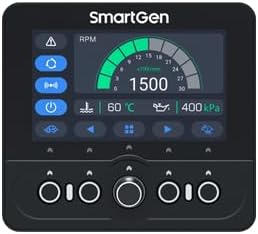
Figure 1: EP4300 Front Panel
3.2 Арткы панель жана байланыштар
The rear panel provides various ports for power, sensors, communication, and auxiliary inputs/outputs, facilitating integration into engine systems.

Figure 2: EP4300 Rear Panel with Connection Labels

Figure 3: EP4300 Side View
4. Орнотуу жана зымдар
Proper installation and wiring are crucial for the correct operation of the EP4300 controller. Ensure all connections are secure and follow the provided wiring diagram.
4.1 Typical Application Diagram
The diagram below illustrates a typical wiring configuration for the EP4300, showing connections for power, sensors, CANBUS, RS485, and auxiliary I/O. Refer to this diagram for detailed wiring instructions.

Figure 4: EP4300 Typical Application Diagram
- Электр камсыздоо: Connect the controller to a stable DC power source (B+ and B- terminals).
- Сенсорлор: Connect engine sensors (e.g., oil pressure, water temperature, fuel level) to the designated sensor inputs (SENSOR1, SENSOR2, SENSOR3). Note that SENSOR3 supports resistance, voltage, or current, while SENSOR1 and SENSOR2 are for resistance sensors.
- Магниттик пикап: Connect magnetic pickup sensors to MP1 and MP2 for engine speed detection.
- КАНБУС: Connect CAN H and CAN L to the engine's J1939 CANBUS interface for communication with electric-controlled engines.
- 485: Use the RS485 interface for PC communication or integration with other devices.
- USB: The USB port allows for parameter configuration and data download via PC.
- Көмөкчү киргизүү/чыгаруу: Utilize auxiliary inputs and outputs for custom control and monitoring functions as per your application requirements.
Note: For speed control and instrument mode, an external start/stop device must be added.
5. Операция
5.1 Күйгүзүү/өчүрүү
To power on the controller, ensure the power supply is connected correctly. The unit will automatically initiate its startup sequence. To power off, disconnect the main power supply to the controller.
5.2 Дисплей навигациясы
The 4.3-inch color LCD displays real-time engine parameters and operational status. Use the physical buttons and the rotary knob on the front panel to navigate through menus, view different screens, and select options.
5.3 Параметрди тууралоо
Many operational parameters can be adjusted directly from the front panel using the display and control buttons. For comprehensive configuration and advanced settings, connect the controller to a PC via the USB or RS485 port and use the SMARTGEN configuration software.
5.4 Тил жана жарык орнотуулары
The controller supports both Chinese and English languages. You can switch between languages through the system settings menu on the LCD. The display backlight intensity can also be adjusted manually or set to automatic adjustment via the same menu.
6. Техникалык тейлөө
- Тазалоо: Regularly clean the controller's front panel and display with a soft, dry cloth. Avoid using abrasive cleaners or solvents that could damage the screen or buttons.
- Туташуу текшерүүлөрү: Periodically inspect all wiring connections to ensure they are secure and free from corrosion. Loose connections can lead to intermittent operation or inaccurate readings.
- Экологиялык шарттар: Ensure the controller operates within its specified environmental conditions (temperature, humidity) to prevent damage and ensure longevity.
- Программалык камсыздоонун жаңыртуулары: Өндүрүүчүнү текшериңиз webиштин натыйжалуулугун жакшыртуучу же жаңы функцияларды кошуучу ар кандай жеткиликтүү программалык камсыздоо жаңыртуулары үчүн сайт.
7. Кыйынчылыктарды
This section provides solutions to common issues encountered with the EP4300 Engine Controller.
- Контроллер күйбөй жатат:
- Verify that the power supply (B+ and B-) is correctly connected and providing the specified voltage.
- Check for any blown fuses in the power circuit.
- Display is Blank or Unresponsive:
- Контроллер күйгүзүлгөнүн текшериңиз.
- Adjust the backlight settings to ensure it's not set too low.
- If the issue persists, power cycle the unit.
- Туура эмес сенсордук көрсөткүчтөр:
- Check the wiring of the specific sensor for loose connections or damage.
- Verify that the sensor type and calibration settings in the controller match the installed sensor.
- Ensure the sensor itself is functioning correctly.
- CANBUS байланыш каталары:
- Confirm CAN H and CAN L connections are correct and secure.
- Check for proper termination resistors on the CANBUS network if applicable.
- Verify that the engine's ECU is powered and communicating.
For issues not covered here, or if troubleshooting steps do not resolve the problem, please contact SMARTGEN technical support.
8. Техникалык шарттар
| Спецификация | Нарк |
|---|---|
| Бренд | АКЫЛДУУ ЖАНА |
| Модел | EP4300 |
| Элемент Салмагы | 15.8 унция (0.45 килограмм) |
| Материал | Жез |
| Дисплей | 4.3-inch Colour LCD, 480x272 resolution |
| Процессор | ARM негизиндеги 32-биттик SCM |
| Коммуникация интерфейстери | CANBUS (J1939), RS485, USB |
| Analog Sensor Inputs | 3 programmable (Sensor 3: resistance/voltage/current; Sensor 1/2: resistance) |
9. Кепилдик жана колдоо
The SMARTGEN EP4300 Engine Controller is manufactured by SMARTGEN. For warranty information, technical support, or service inquiries, please contact SMARTGEN directly through their official support channels. Please retain your proof of purchase for any warranty claims.


